


Isolated MOSFETs MOS Tube Field Effect Transistor Module Replacement Relay Fr120n Lr7843 D4184
Isolated MOSFETs MOS Tube Field Effect Transistor Module Replacement Relay Fr120n Lr7843 D4184
Understanding Isolated MOS Tubes & Field Effect Transistors
What are Isolated MOS Tubes?
Isolated MOS tubes, also known as Insulated Gate Bipolar Transistors (IGBTs), are semiconductor devices that combine the advantages of MOSFETs and bipolar transistors. They offer low on-state voltage drop, high input impedance, and fast switching speeds. In this article, we will focus on the Isolated MOS tube, which is a specific type of MOSFET designed for applications requiring isolation between the control circuit and the power circuit.
How do Field Effect Transistors Work?
Field Effect Transistors (FETs) are electronic components that control the flow of current using an electric field. There are two types of FETs: Junction Field Effect Transistors (JFETs) and Metal-Oxide-Semiconductor Field Effect Transistors (MOSFETs). MOSFETs are more widely used due to their high input impedance and ease of integration into integrated circuits.
MOSFETs consist of three terminals: source, gate, and drain. The voltage applied to the gate terminal controls the flow of current between the source and drain terminals. When the gate-to-source voltage exceeds a certain threshold, the channel between the source and drain becomes conductive, allowing current to flow. By varying the gate-to-source voltage, the current flowing through the MOSFET can be controlled.
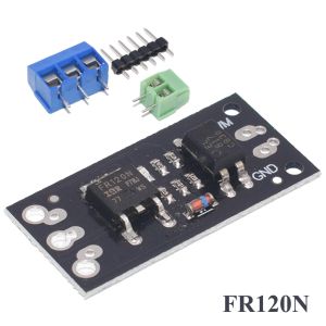
FR120N LR7843: A Closer Look
FR120N LR7843 Specifications
The FR120N LR7843 is a high-performance N-channel MOSFET designed for power switching applications. Some of its key specifications include:
- Maximum drain-to-source voltage (VDS): 120 V
- Continuous drain current (ID): 18 A
- On-state resistance (RDS(on)): 0.018 Ω
- Maximum gate-to-source voltage (VGS): ±20 V
Applications of FR120N LR7843
The FR120N LR7843 is suitable for a wide range of applications, including:
- Power supplies
- Motor drives
- Solar inverters
- Battery chargers
MOSFET Module Replacement: Step-by-Step Guide
Preparing for MOSFET Module Replacement
Before replacing a MOSFET module, ensure that the power supply is disconnected and the circuit is discharged. Gather the necessary tools, including a screwdriver, soldering iron, and replacement MOSFET module.
Replacing the MOSFET Module
- Remove the old MOSFET module by unsoldering its connections.
- Install the new MOSFET module by soldering its connections.
- Check the connections for any shorts or open circuits.
Testing the New MOSFET Module
After replacing the MOSFET module, test the circuit to ensure proper operation. Measure the voltage drop across the MOSFET and verify that the current flowing through it is within the specified limits.
Relay Module D4184: Installation & Maintenance
Installing Relay Module D4184
To install the relay module D4184, follow these steps:
- Connect the power supply to the relay module.
- Connect the load to the relay contacts.
- Connect the control signal to the relay coil.
Maintaining Relay Module D4184
To ensure the proper operation of the relay module D4184, perform regular maintenance tasks, such as:
- Inspecting the relay contacts for signs of wear or damage.
- Cleaning the relay contacts if necessary.
- Verifying the proper operation of the relay coil.
Troubleshooting Common Issues
Some common issues that may occur with the relay module D4184 include:
- Relay contacts sticking: This can be caused by dirt or corrosion on the contacts. Clean the contacts and inspect them for damage.
- Relay coil failure: This can be caused by excessive voltage or current. Verify the proper operation of the control signal and power supply.

TB supermarket store
Review

You May Also Like
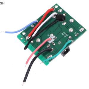
🚗🛵SH 5S 18V 21V 20A Battery Charging Protection Board Protection Circuit Board
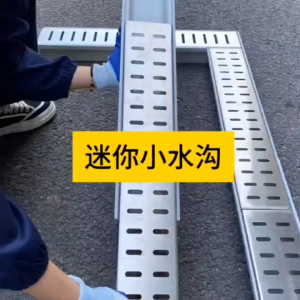
【Ready Stock】Stainless Steel Cover Resin Drainage Gutter | U-Groove Linear Drain with Grating

👉Waterproof 50 years👈Waterproof glue sealant 500g Transparent invisible Waterproof leak trap Repair cracks roofs floors walls. transparent water proof glue super waterproof glue sealant sealant waterproof roof leak waterproof sealant

High Pressure Shower Head Heart Ring Spray Booster Shower Heads Bathroom Rain Shower Mixer Bathroom Accessories
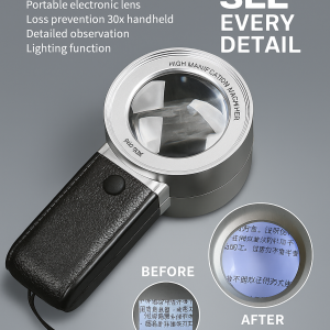
30x Handheld Portable Magnifying Glass LED Light HD Optical Microscope High Magnification HD Optical Tool

30cm Big Size Aluminum Foil Butyl Waterproof Taperoof Leaks Water Proofing Sealant Sink Fix Repair Wall Crack Material
![[COD] SHGMYD 2Pcs 18650 Lithium Battery Spot Welder Electrode Tip for High Detailed Projects](https://img.lazcdn.com/g/p/e60a3cb6cdecbf00dd7a1b7ae256ae9a.jpg_300x300q80.jpg)
[COD] SHGMYD 2Pcs 18650 Lithium Battery Spot Welder Electrode Tip for High Detailed Projects

SINCLAIR BAHAGHARI (16L)
![[COD] SHGMYD LD-600S Build-in 3 Way Finger Touch Dimmer ON/OFF Switch US EU](https://img.lazcdn.com/g/p/5659a44cee08d4affd1095a89b244940.jpg_300x300q80.jpg)
[COD] SHGMYD LD-600S Build-in 3 Way Finger Touch Dimmer ON/OFF Switch US EU

Original ZK UF100 Face Recognition Time Attendance System With Fingerprint Reader TCP/IP Facial Time Clock WIFI Free
CROWMSTAR Rechargeable Lithium Battery 3S2P 11.1V 5000mAh: A Comprehensive Guide