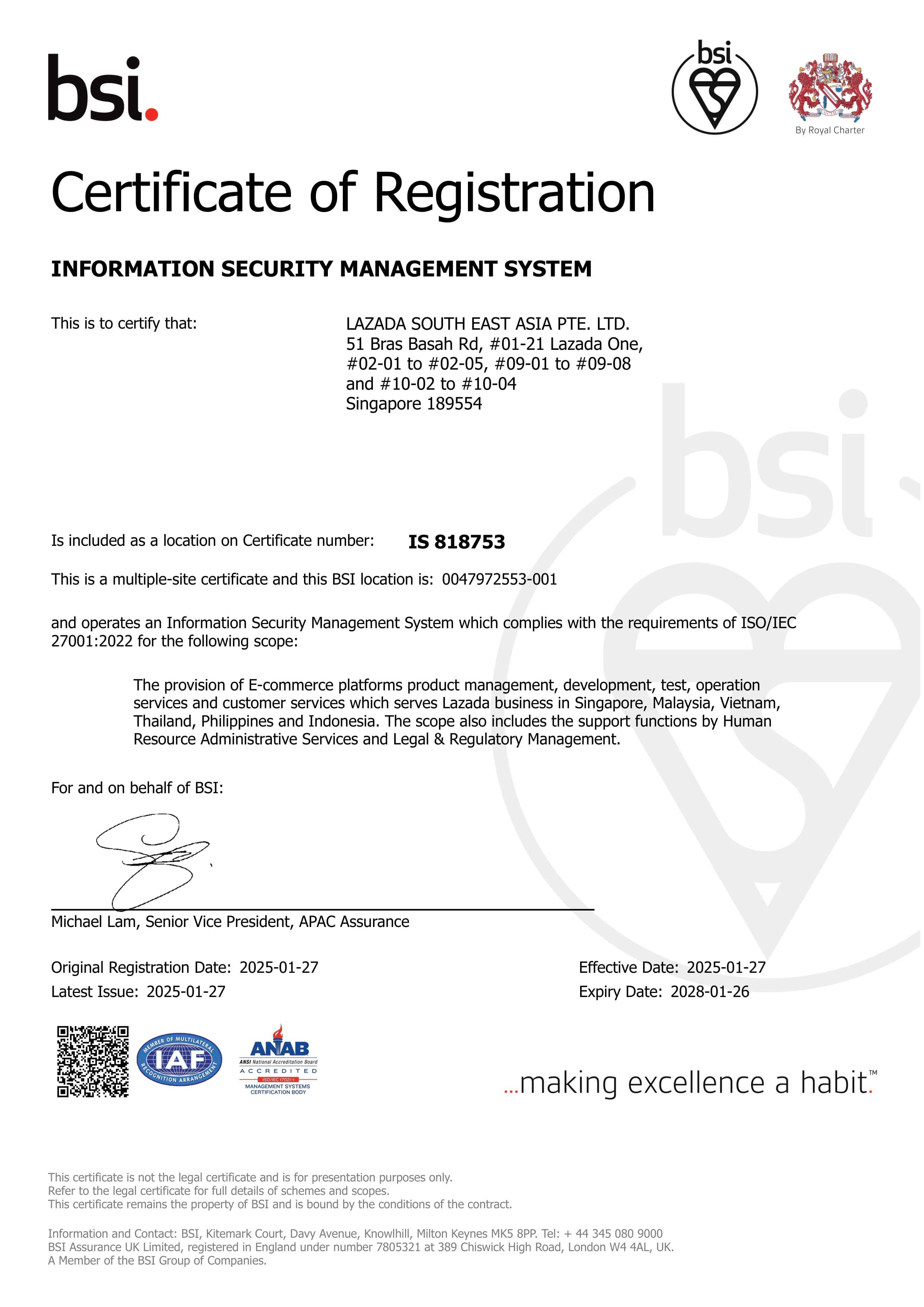


Beseyun LJM L15DSMD IRS2092S 250W Class D Mono Digital Power Amplifier Board

Beseyun LJM L15DSMD IRS2092S 250W Class D Mono Digital Power Amplifier Board
L15DSMD IRS2092S 250W Class D Mono Digital Power Amplifier Board
Recommended working voltage and transformer power.

The load is 8 ohms, the transformer voltage is AC 40V, +-DC 55V, and the power is 150W per channel.300W two channels.Filter capacitor 6800UF*2 or more

Load 4 ohms, transformer voltage AC dual 35V, + -DC 48V power 250W per channel.500W two channels.Filter capacitor 10000UF*2 or more

Load 4 ohm + -58V DC, 300W 4R mono power.700W dual-channel power.The recommended transformer voltage is AC dual 41V 1000W.


It uses IRS2092S and IRFI4020H digital power amplifier dedicated chips.All use high-quality imported chips, MOSFETs.Large-capacity aluminum electrolytic capacitors imported from Japan.

Parameter introduction:

Operating voltage DC + -50V (between + -33V and + -55V) + -50V OUTPUT power = 125W 8R RMS.250W 4R RMS.

Size: length, width and height: 100MM*58MM*42MM

The distance of the mounting holes is: 91.5MM horizontal, 49.5 MM vertical

Distortion: Distortion: 0.007% THD+N @ 60W, 4 Ω

Voltage gain: Voltage Gain 36

Load Impedance Drive impedance: 4 Ω

Total Idle Power Consumption, no-load idle power consumption: 7W

Channel Efficiency: 90% 250W 4 Ω

Dynamic Range: 101 DB

Residual Noise: 200UV

Frequency Response: 20HZ-35K HZ + -3DB

Temperature performance: Thermal Performance: 30W power, 55C degrees Celsius

250W power, 90C degrees Celsius


The figure below has a white background, this is the actual measurement data of LJM

The voltage is + -50V and the impedance is 8 ohms.If you are interested, you can download the big picture.

Actual measurement of L15DSMDV3 version

When the THD+N output power is about 10.1 V RMS

THD+N = 0.006%- 0.008% or so


Frequency response graph-actual measurement: (The digital power amplifier will have a little upward gain when measured in an 8 ohm load due to the filter, which will not be displayed in 4 ohms.This measurement data is consistent with the IR)
Comparison of test images of the DEMO version of the IR company:
THD+N Test Chart
HD+N distortion plus noise amplitude value graph can be understood as a dynamic distortion graph.The white background is the actual LJM measurement.The yellow background is the sample of the IR company, which can be used as a comparison


THD+N Test Data


Use the latest specification digital power amplifier special inductor, 14A current 0.013 ohm impedance value.

Fully shielded, low radiation, low distortion design.

Use IR's D-type program design model IRAUDAMP7S as a template.

Using high-end class D amplifier driver IC IRS2092.Achieve the current minimal distortion, the maximum output power of 500W.

Use IR standard configuration MOSFET audio dedicated MOSFET output tube, MOSFET.

By providing the new IRFI4xxxH-117P series of MOSFET half-bridges, IR has improved many performances of Class D audio power amplifiers.
The integrated half-bridge package mode reduces the number of components in half and improves the PCB layout.In addition to lower on-resistance, this series of MOSFET half-bridges also have optimized gate charge, parasitic diode reverse recovery capability and internal gate resistance.These have improved the performance and effect of Class D audio amplifiers, the main parameters such as working efficiency, total harmonic distortion and electromagnetic radiation. The typical on-resistance RDS(ON) of IRFI4xxxH-117P is 80 mOhms, and the typical gate charge is 13NC, and the switch charge is 4.1NC.
Adopt high-power, high-current, low-impedance fully shielded inductors dedicated to digital power amplifiers.It has a very small resistance value=0.013 ohm actual measurement, current=14A.Very small radiation and interference, large current, and higher frequency operating parameters.

Make the distortion of the digital power amplifier reach the lowest level.

Beseyun Mall
Seller ratings 87%
Review

Oops
This video has no reviews.
You May Also Like
00:57
MUSICER TX-SUB5 5.25 inches 300 watts Dual Cone 4 ohms Car SUBWOOFER Speaker
00:20
NANATECH XB203 PRO Portable Bluetooth Speaker with Superbass and LED Lighting Waterproof IPX7 Rugged Design
00:26
Portable Magnetic Bluetooth Speaker Mini Stereo Sound Wireless Home Outdoor Travel Soundbox Convenient Carry-On Audio Device
00:52
FTstar AV-502B 5.1 Channel Karaoke Amplifier 3000 Watts 100% Original
00:52
DORADO 7/10/12 Inch Vinyl Record LP Jackets Brown Kraft Paper Cardboard Vinyl Record Covers Records Inner Outer Sleeves

00:22
Speaker BTS-2241 Brodu 12 inch Bluetooth Speaker With 2 Rechargeable Wireless Microphone For Audio

00:50
Head Phones Bluetooth Headset Wireless Earphones with Mic Support TF Card Stereo On-Ear Chargeable Headphones Headset Gaming For PC
00:46
POPCORN BASS X8 PRO 1BA+1DD in Ear Monitor TYPE-C HiFi Wired Earbuds 3.5mm Gaming Earbuds Hybrid IEM Earphones 2 Pin Detachable Cable (With Mic Black)
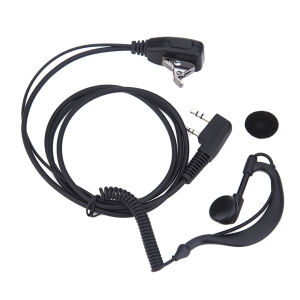
00:17
2 PIN Earpiece Headset PTT MIC Walkie Talkie Headset with Microphone 1M Walkie Talkie Earbud Walkie Talkie Headphone for Baofeng UV5R
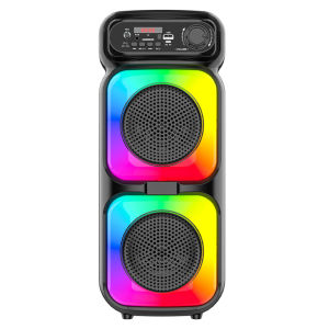
00:30
BT Wireless Speaker Support MIC/TF/USB/AUX Portable Speaker with Microphone for Party Outdoor Travel Birthday Gift
00:39
Portable Wireless In-ear Monitoring System Stage Monitoring Headphones Stereo 2.4G Real-time Latency-free IEM System
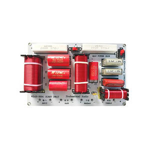
00:13
【Free Shipping】 Hi-Fi Grade Audio Frequency Divider 480W HiFi Speaker Crossover for Home Stereo
Hot Search
Joieclassic signal lightsSolar Wind Power Best Pricecap woman nyc blackBINCOOyamang mineral chartpiranha tidy tail yamaha mt15citrus fertilizersblue archive redmi casestrapless tube seamless braglutathione capsules with biotincm octopus disco lights70s retro fashionkubota l1500 partsnon slip bathroom tile stickers