


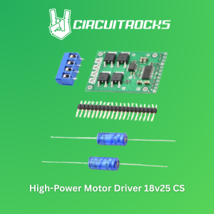
Circuitrocks High-Power Motor Driver 18v25 CS Pololu
The Pololu high-power motor driver is a discrete MOSFET H-bridge designed to drive large DC brushed motors. The H-bridge is made up of one N-channel MOSFET per leg, and most of the board’s performance is determined by these MOSFETs (the rest of the board contains the circuitry to take user inputs and control the MOSFETs). The MOSFET datasheet is available under the “Resources” tab. The MOSFETs have an absolute maximum voltage rating of 30V; higher voltages can permanently destroy the motor driver. Under normal operating conditions, ripple voltage on the supply line can raise the maximum voltage to more than the average or intended voltage, so a safe maximum voltage is approximately 24V.Note:Batteries that are nominally 24V can be much higher than that when fully charged; this product is therefore not recommended for use with 24V batteries unless appropriate measures are taken to limit the peak voltage.The versatility of this driver makes it suitable for a large range of currents and voltages: it can deliver up to 25A of continuous current with a board size of only 1.8" by 1.2" and no required heat sink. With the addition of a heat sink, it can drive a motor with up to about 40A of continuous current. The module offers a simple interface that requires as few as two I/O lines while allowing for both sign-magnitude and locked-antiphase operation, and an optional third control input unique to this board allows for coasting. This board also features acurrent-sensing circuitthat measures bidirectional motor current with a magnitude up to 30A and outputs an analog voltage.Integrated detection of various short-circuit conditions protects against common causes of catastrophic failure; however, please note that the board does not include reverse power protection or any over-current or over-temperature protection. We recommend you use the integrated current sensor to keep the driver from delivering more current than it can safely handle.Using the Motor DriverConnectionsThe motor and motor power connections are on one side of the board, and the control connections (5V logic) are on the other side. The motor supply should be capable of delivering the high current the motor will require, and a large capacitor should be installed between V+ and ground close to the motor driver to decrease electrical noise. Two axial capacitors are included and one or both can be installed by soldering them into the V+ and GND pins (labeled '+' and '-' on the bottom silkscreen) along the long edges of the board. Such installations are compact but might limit heat sinking options; also, depending on the power supply quality and motor characteristics, a larger capacitor might be required. There are two options for connecting to the high-power signals (V+, OUTA, OUTB, GND): large holes on 0.2" centers, which are compatible with the included terminal blocks, and pairs of 0.1"-spaced holes that can be used with perfboards, breadboards, and 0.1" connectors.Warning:Take proper safety precautions when using high-power electronics. Make sure you know what you are doing when using high voltages or currents! During normal operation, this product can gethotenough to burn you. Take care when handling this product or other components connected to it.The logic connections are designed to interface with 5V systems (5.5V max); the minimum high input signal threshold is 3.5V, so we do not recommend connecting this device directly to a 3.3V controller. In a typical configuration, only PWMH and DIR are required, but PWML can be used to enable coasting if both PWML and PWMH are driven low. PWML is pulled high and PWMH is pulled low internally. The two fault flag pins (FF1 and FF2) can be monitored to detect problems (see the Fault Flag Table below for more details). TheRESETpin is pulled up to V+ through a 20kΩ resistor. When held low, it puts the driver into a low-power sleep mode and clears any latched fault flags. The V+ pin on the logic side of the board gives you access to monitor the motor’s power supply or pass it on to low-current devices (it should not be used for high current). The board also provides a regulated 5V pin which can provide a few milliamps (this is typically insufficient for a whole control circuit but can be useful as a reference or for very low-power microcontrollers). This pin can be shorted to VCS to power the current sensor, or VCS can be supplied with 5V externally. If the 5V output pin is used to power VCS, it should not be used for any other purpose as the current sensor will draw close to the limit of the current the 5V pin can supply. When the current sensor is powered by applying 5V to VCS, the CS pin outputs 66mV/A for currents between -30 and 30A centered at 2.5V (typical error is less than 1.5%).

circuitrocks
Review

You May Also Like
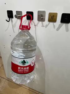
4/1pcs Stainless Steel Bathroom Robe Hooks Adhesive Wall Hook Towel holder Bathroom Kitchen Hardware Multi-Purpose Hanger Hook

SJJL MALL Stainless Steel Paint Roller Extension Pole 170/205/240cm Detachable Latex Paint Brush Set Roller Brush Tapered Adapter Paint Roller Painting

Grease Gun 400-600CC Grease Gun Pump Heavy Duty High Pressure Oil Injection Grease Gun Pump Greasing Tools

【PHYTR】 Injection Base Carbon Carbon Fiber RTM Vaccum Resin Infusion Inject Base Silicone Connector

SIDSI 300/400/500MM Toilet Handrail With Anti Slip Texture Stainless Steel Shower Safety Support Handle Towel Rack Black Bathroom

Digeo 5Balls/7 Balls Display Organizer Hooks Waved Clothes Hanger Storage Rack
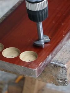
Drill Bits 15/20/25/30/35mm5PCS Auger Drill Forstner Bit Set Hinge Boring Woodworking Hole Saw Cutter Round Shank Wood Tools
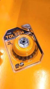
Tolsen Industrial Cup Twist Wire Brush with Nut (75mm | 100mm | 125mm - M10 | M14 & Ø3" | 4" | 5" - 5/8"-11)
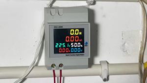
6IN1 Din Rail AC Monitor 110V 220V 380V 100A Voltage Current Power Factor Active KWH Electric Energy Frequency Meter

Piano Button Digital Display Constant Temperature High Pressure Shower Set
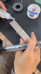
Stainless Steel Flux 30ml 80ml Quick Repair Strong Solder Liquid Battery Electrode Soldering Welding