


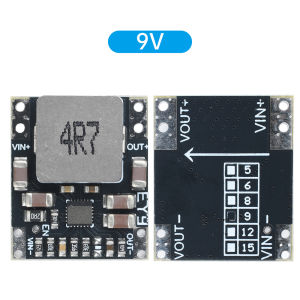
diymore | DC-DC automatic buck boost power module 3-23V to 5V/9V/12V fixed voltage output lithium battery constant voltage module
Features:1. DC-DC automatic voltage boosting module, with a wide input voltage range (3-23V), suitable for various power supply scenarios.2. Fixed voltage output is optional, with a maximum output current of 5A, supporting high-power devices.3. Operating frequency of 500KHz, full load ripple less than 100mV, stable and reliable output.4. It is recommended to keep the usage within 3A for a long time, and increase heat dissipation if it exceeds 3A to ensure the lifespan of the module.5. Compact in size, with a double hole spacing of 2.54mm, suitable for wire bonding or PCB mounting.Parameter:Type: DC-DC power moduleInput voltage: 3-23V (minimum input voltage of 2.6V to start the chip, discharge to 2.4V to stop output) The smaller the input and output voltage difference, the lower the heat generation and the higher the efficiency.Output voltage: 5V/9V/12V fixed voltage output (non adjustable)Output current: Maximum 5A (long-term use should be controlled within 3A with a power of 25W. If the power exceeds this limit, please increase heat dissipation. It is recommended to attach the back of the board to the outer shell of an iron or aluminum plate to increase heat dissipation, and be careful not to short-circuit underneath)Full load ripple:Working frequency: 500KHZInput current: maximum 4AOutput current: maximum 5ASize: 20 L * 17 W * 5.6 H MMPackage Include:1X moduleModule description and usage precautions:1. The spacing between the dual holes of the module is 2.54MM2. Can be attached to PCB board for use3. The negative pole of the module is common ground4. Do not connect the input terminal to the opposite positive and negative poles, as doing so will cause overheating.5. The solder pads on the front of the module are relatively small, so be careful not to touch inductors and other components during soldering as it may burn the chip6. If using boost mode, ensure reliable welding of the wiring, with short and thick wires to ensure sufficient input current.7. Connect a 470UF/25V electrolytic capacitor in parallel at the input of the module (near the module) and connect 100UF or 220UF/25V in parallel at the output of the module8. This module is not suitable for inductive loads such as motor relays, speakers, etc. Reverse voltage will break down the chip, and you can search online for the reverse electromotive force of principle one motor. Here is just a solution: it requires parallel TVS tubes or diodes at the output end. Try to choose a large package (TVS tube has a service life) (bidirectional TVS tube, the voltage of TVS tube is 2 volts higher than the output voltage, a little larger is also acceptable)+electrolytic capacitor 100UF or 220UF is used in parallel.

Prime Supply_Play Life
Review

You May Also Like
AUK HY510 YJ-G190 Grey Thermal Paste for CPU GPU Cooler Cooling Heatsink Paste 25g 10g
2pcs Server Fan 8CM 2 Wires Ultra-Quiet Welding Cooling Fan For Welding Machine Daily Exhaust Work

HUANANZHI | X99-BD3 Motherboard LGA2011-3 4 DDR3 Slots 128GB RAM PCIE 3.0 NVME SATA3.0 Mainboard

19/20/21.5 /23.6 Inch Led Monitor HD 900P / FHD 1080P 60HZ Monitor For PC Computer Laptop N200HD
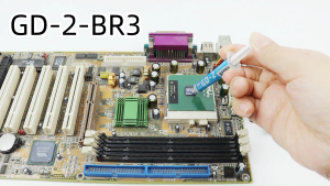
GD-2 High Performance Thermal Grease 7.5 W/m·K 3g CPU GPU PS5 Printer Heat Sink Compound BR3
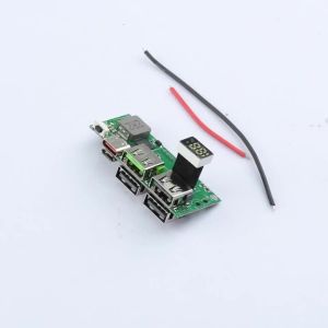
22.5W Super Fast Charging/PD 20W Bidirectional Module IP5356 for 3.7V Battery Power Banks (DIY) USB+Type-c+Micro port
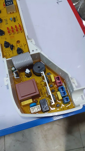
Haier PCB board Z918

MINISFORUM N5 PRO NAS /N5 R7 255 Mini PC AMD Ryzen™ AI 9 HX 370/AMD Ryzen™ 7 255 Dual 2.5G LAN Multiple M.2 NVMe SSD Slots
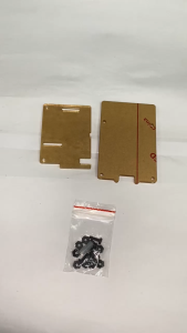
Circuitrocks Pi Protector for Raspberry Pi Model B + / Pi 2 / Pi 3

ICE Whale WX-3 Wire-Splicing PC Case Cooling Fan 3PIN ARGB Mirror Cycle Light Effect 800-1600RPM PWM Water Cooling Cooler Fan

DIY Kit Electronics Components CJMCU CP2102 Type-C MICRO USB To UART TTL Module 6Pin Serial Converter UART STC Replace FT232